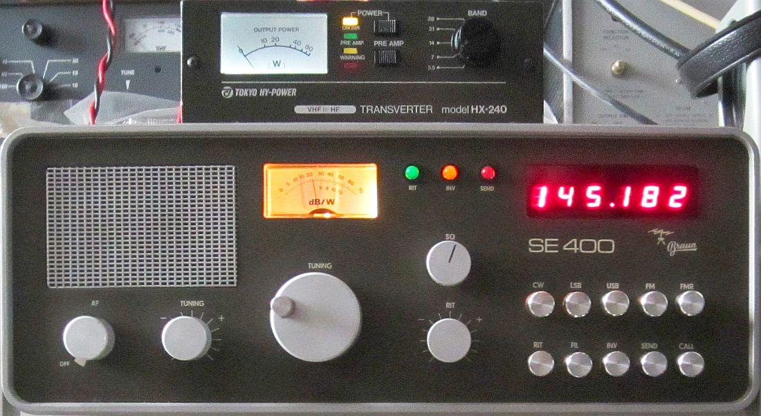
HY-POWER TRANSVERTER HX-240, MAKEOVER
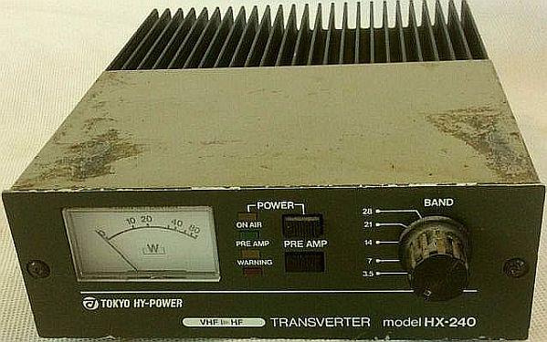
This was offered on eBay in 2019.
INTRODUCTION
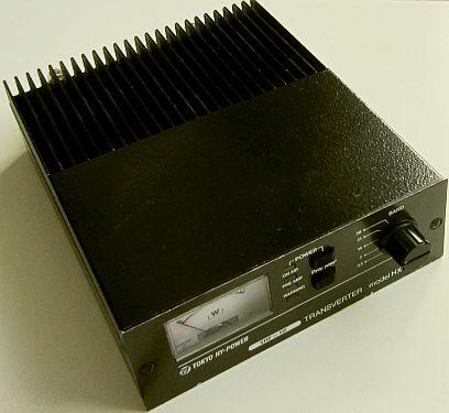
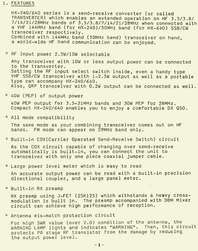
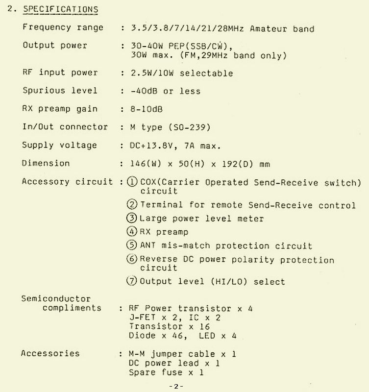
The manufacturer TOKYO HY-POWER (THP) has made many beautiful HF/VHF amplifiers with tubes and transistors, but also other equipment such as an HX-240 transverter in 1990. This converts a 2 m signal to the five pre-WARC amateur bands. The manufacturer went bankrupt in 2013 due to the economic slump at the time. Originally it was founded in 1975 by JA1DJW and focused on production for amateur radio.
The technical design of such an HX-240 has always had my interest, but it was not cost-effective to purchase the device for this until the HX-240 shown above was offered on eBay. Given the appearance there were not many bidders, so it came into my possession.
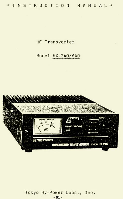
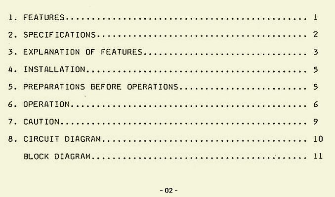
MANUAL AND SCHEMATICS
Because it is an vintage device, there is little technical information about it and even the original TOKYO HY-POWER site lacks the model HX-240! Manuals and diagrams on the Internet do not excel in terms of sharpness or readability, which is why it has been incorporated as well as possible in this article.
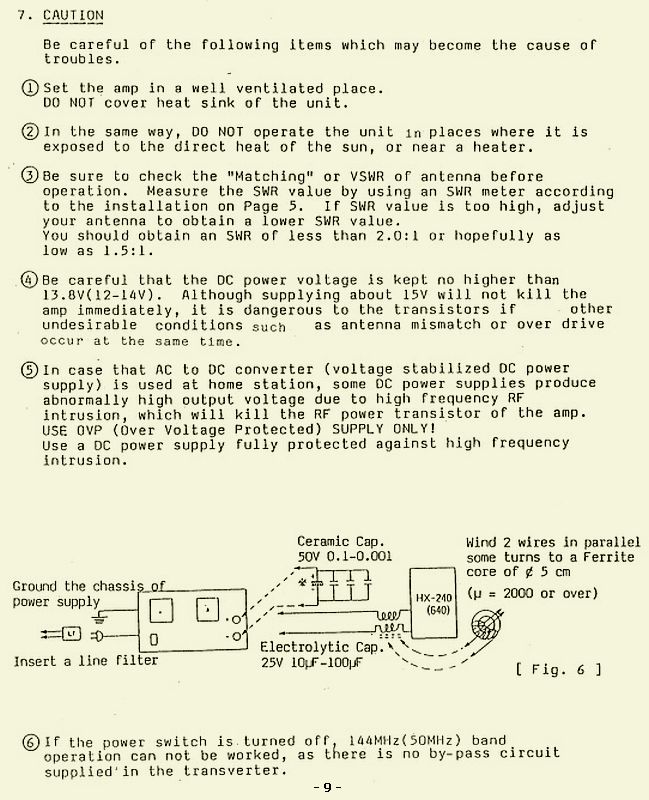
The relevant diagrams are shown below and the rest of the manual can be accessed via the following links:
Page 01, Page 02, Page 1, Page 2, Page 3, Page 4, Page 5, Page 6, Page 7, Page 8, Page 9.
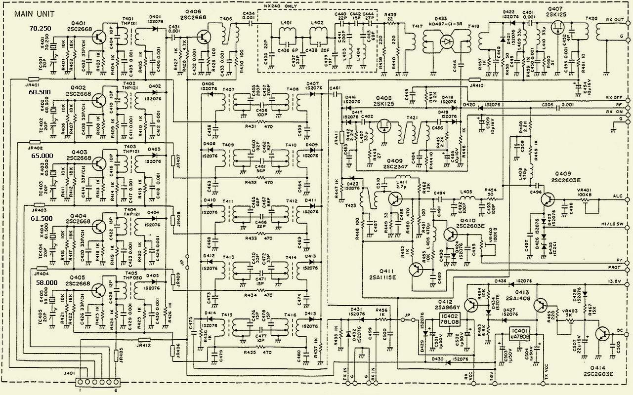
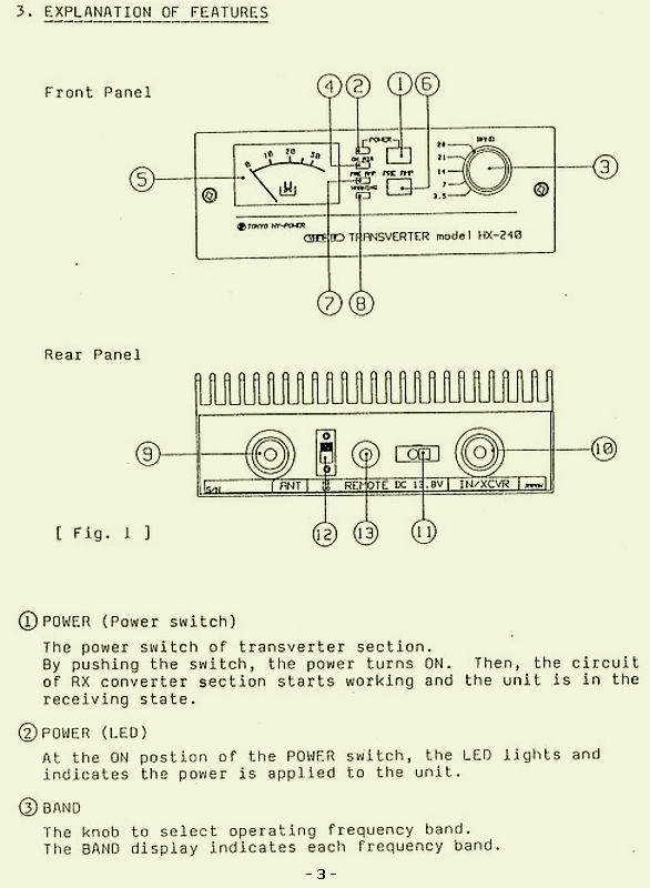
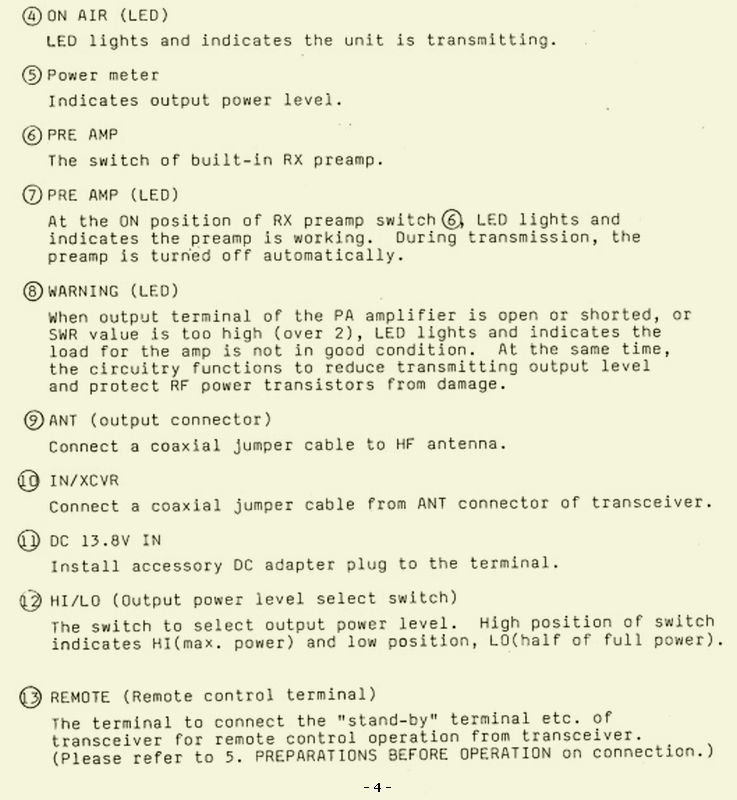
Main Unit.
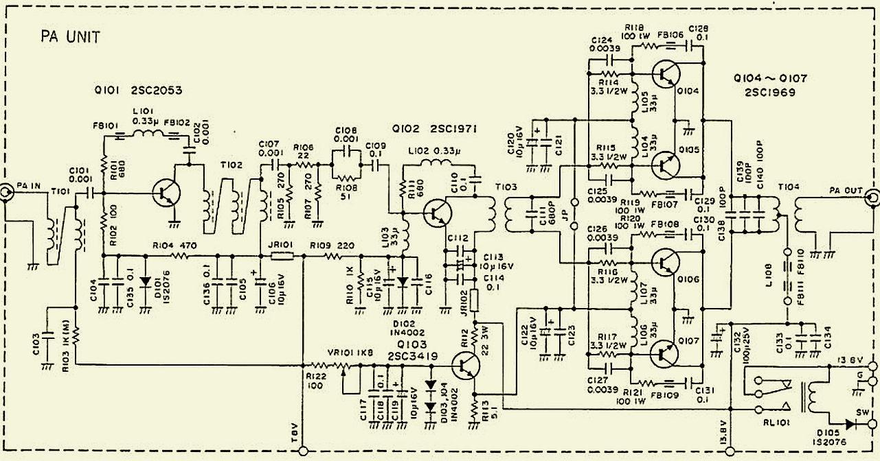
PA Unit
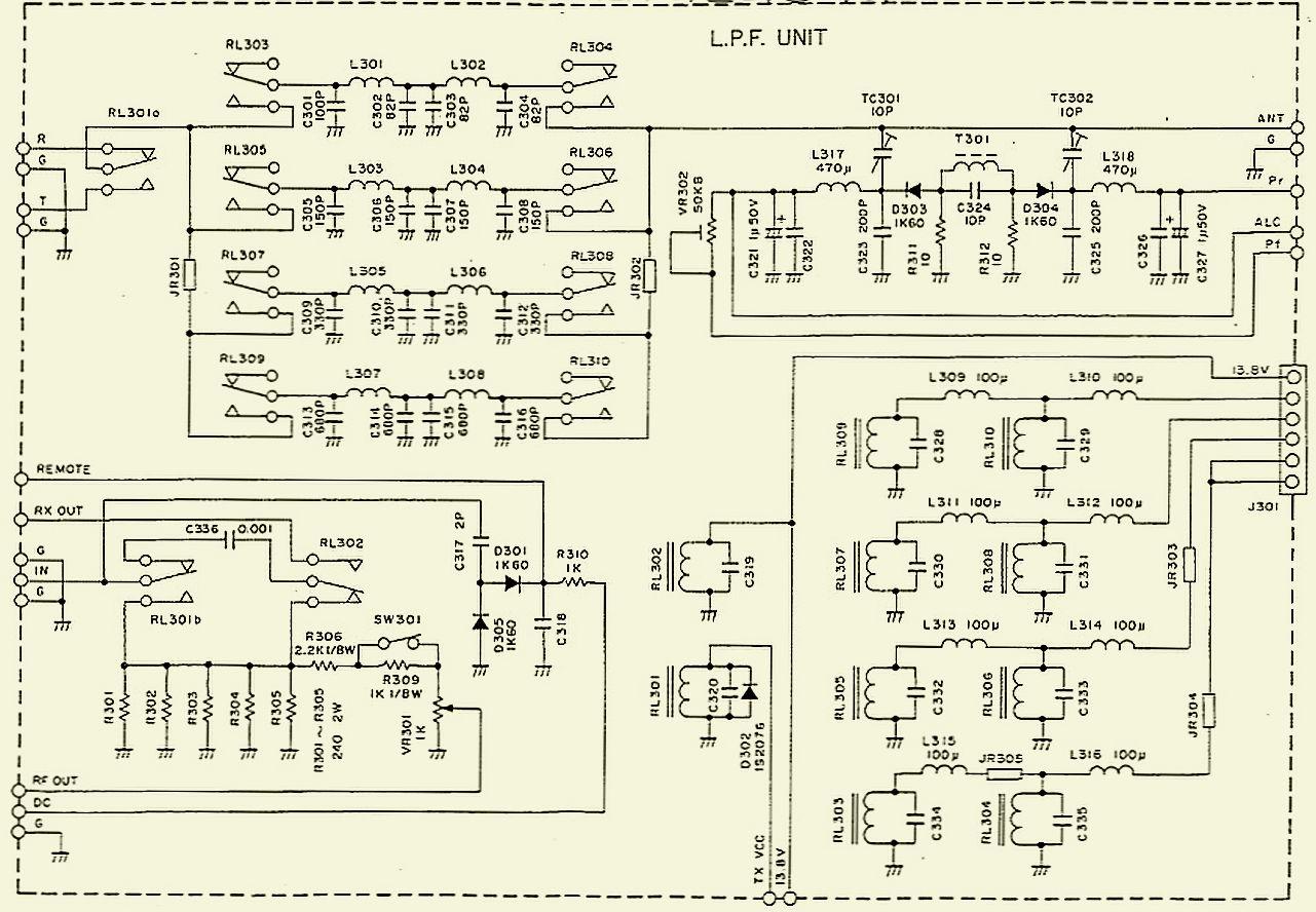
LPF Unit.
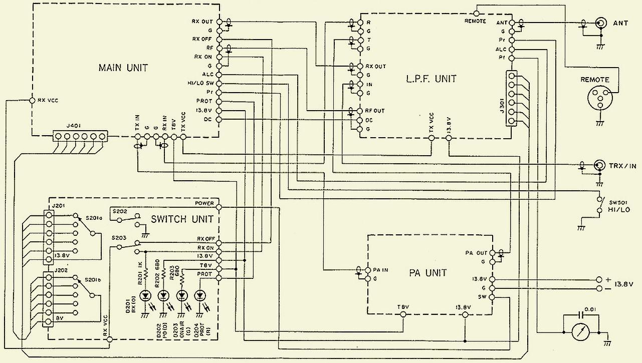
Circuit Unit.
MAIN and PA unit.
.jpg)
LPF unit.
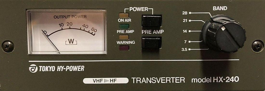
TRANSVERTER HX-240
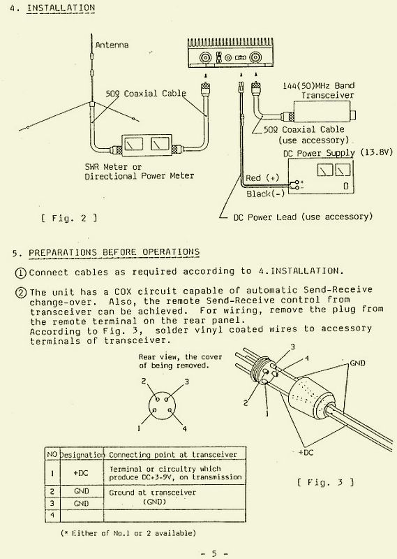
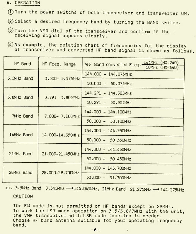
In short, the operation is as follows: the signal from a crystal oscillator is doubled, filtered and mixed with the signal from the 2m transmitter, filtered and then amplified: e.g. 144 - (2 × 70,250) = 3.5 MHz.
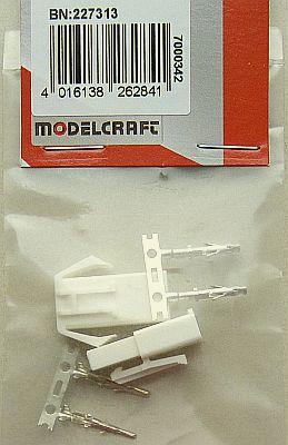
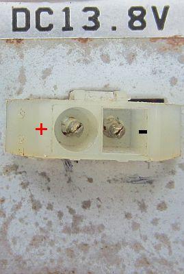
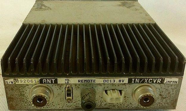
The transverter was delivered without a power cable and I searched intensively on the internet for the type of connector that was installed. Someone on a forum was looking for that too, but never got a definite answer.
In the end, according to the Conrad images, a small easy-to-install connector was chosen and ordered, so that it could possibly be mounted with some extra mechanical work. It is model BN 227313 from MODELCRAFT. The surprise was great when the order was delivered, because it had the same shape as the original and that saved a lot of work.
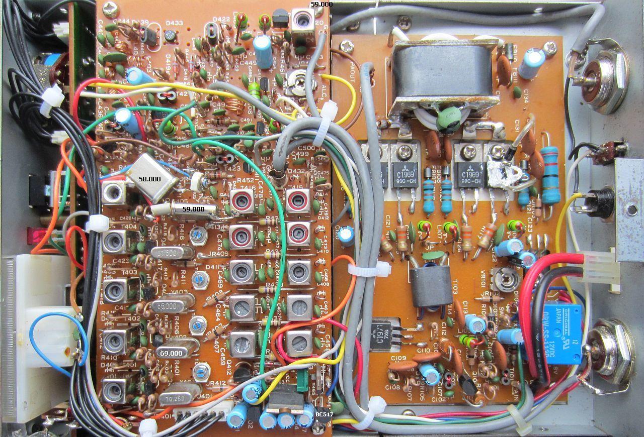
A previous owner has expertly replaced 2 crystals with 59.000 MHz and 69.000 MHz and used the push button for the preamplifier to switch on the CB band.
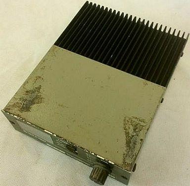
If you buy such an unsightly looking device, the question is what is the state of the inner, but that turned out to be almost virgin.
.jpg)
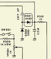
The HX-240 was tested after a thorough cleaning. It all seemed to work well, but the transmission power was less than expected and the COX/VOX system didn't work. It was due to a defective germanium diode D301 on the LPF unit.
Repairing it is quite a job; the PCB must be reversed and then the setback comes, because the majority of the track side is shielded with a soldered metal shield.
Fortunately, that could be solved differently by using a connection wire from the cut-off D301 as a soldering point for the new didode with a wire from diode D305 as the other soldering point.
Without further adjustment with 10 W from a 2 m transceiver the transmitting power was::
| 3.6 MHz | 30 W |
| 7.1 MHz | 38 W |
| 14.1 MHz | 38 W |
| 21.1 MHz | 37 W |
| 28.1 MHz | 27.5 W |
| 27.0 MHz | 14 W |
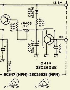
TRANSISTOR Q414
.jpg)
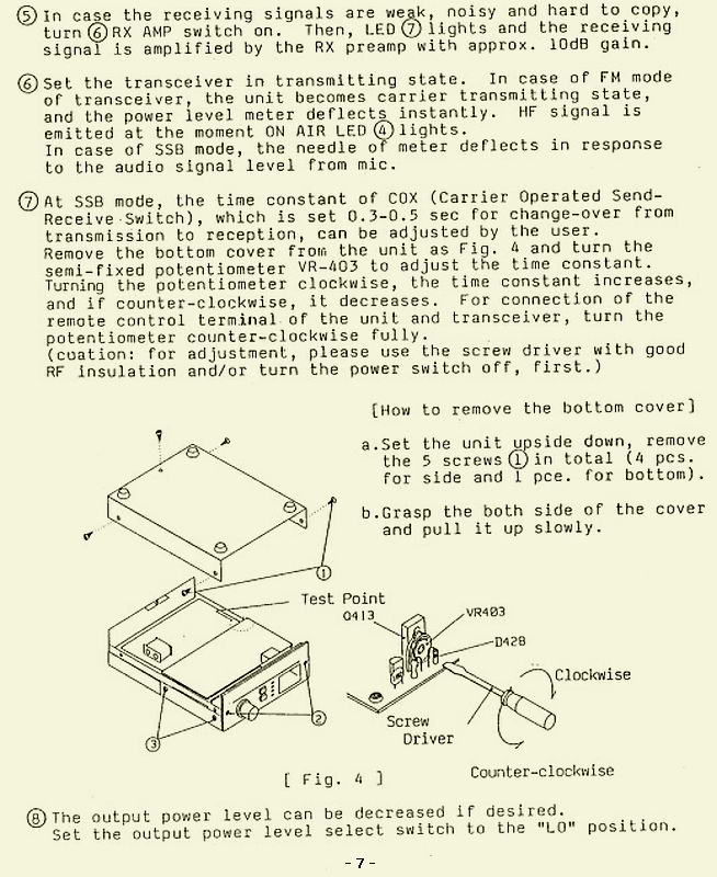
After about 3 - 5 minutes, the relay RL301 spontaneously switched to transmission. In the first instance it is driven by Q414. It took some time before the error was found. It turned out to be the leaking transistor Q414 (2SC2603E). This transistor and elco C507 were actually suspicious. The remarkable thing is that the unsoldered transistor appeared to be OK when measured with a cheap Chinese LCR-T5 component tester. Apparently the leakage in the original circuit only started after heating up by the 8.0 V supply voltage while the tester was working with a voltage of 3.91 V and with that the transistor had an hFE = 279. That was a misleadingly good result! Now that the culprit was finally found, a BC547 was mounted and, to be sure, capacitor C507 was replaced. Please note that the BC547 has a different connection than the original transistor.
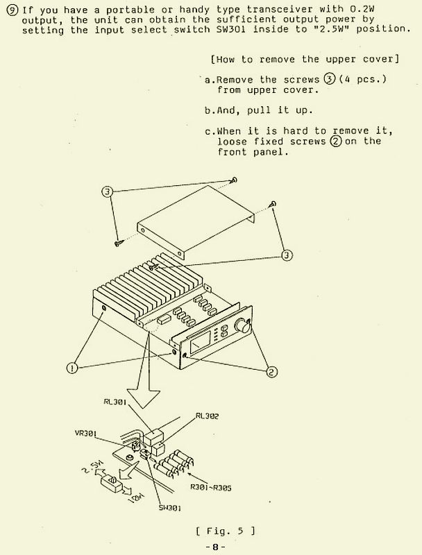
Damaging Q414 may have to do with the failure of diode D301 in the report above. A previous owner has probably run it with 10 W with the internal switch in the 2.5 W position?
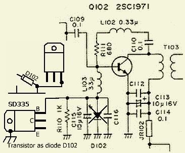
DIODE D102
jpg.jpg)
If the transverter is used intensively, the transmission power in particular is decreasing on the 80 m band. This is largely due to the heating of diode D102 (1N4002). As a result, the setting of driver transistor Q102 changes and the gain decreases. Furthermore, the ferrite of the output transformer T104 becomes quite warm and that apparently also has an influence on the output of that band.
By cooling the area around D102, the output remains more stable. That is why D102 has been replaced by a transistor with a TO-220 housing so that the collector can be mounted directly on the chassis. The basic-collector junction is used as a diode and because the collector is grounded, the "diode" remains more stable. The transistor is a SD335 type, I have a reasonable stock, but it is similar to the BD135 / 137/139 types.
For mounting, one side of diode D102 is cut off and on the other side the wire to the base of the TO-220 transistor is soldered.
It now appears that the transmission power on the five bands is getting closer to each other.
| 3.6 MHz | 30 W |
| 7.1 MHz | 33 W |
| 14.1 MHz | 32 W |
| 21.1 MHz | 36 W |
| 28.1 MHz | 30 W |
| 27.0 MHz | 28 W |
METER LIGHTING
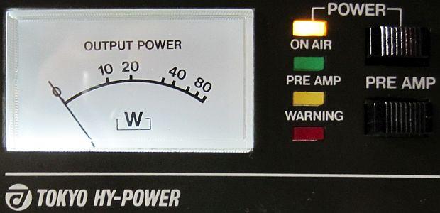
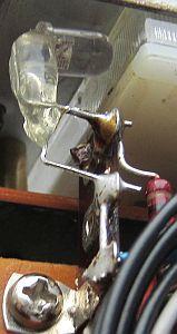
If one is already overhauling, a lighting for the meter may just as well be applied and the box provide with a new hammer-finish paint.
A flattened LED was mounted against the meter at the bottom left. There was no place above the meter unless a flat LED was removed from some lamp or armature. If the LED is mounted on the right side of the meter, the light will disturb the "ON AIR" LED and other pilot lights.
![]()
